3d reference frame change problem
Consider a wheel retracting into an aircraft. The wheel spins relative to a landing gear arm, which itself retracts into the aircraft body.
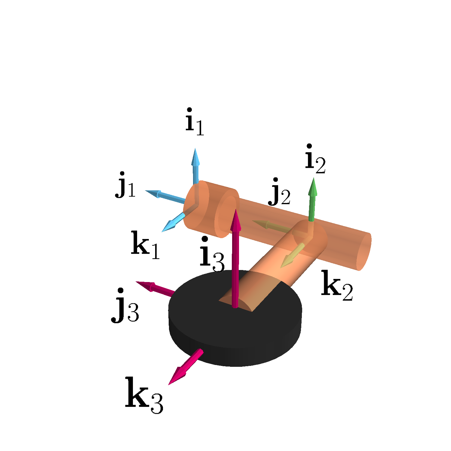
This scenario involves three reference frames:
- frame 1: fixed to the aircraft body,
- frame 2: attached to the landing gear arm,
- frame 3: attached to the spinning wheel.
I’m interested in determining the angular velocity and acceleration of the wheel (Frame 3) relative to the aircraft (Frame 1).
Angular velocity
Let’s denote:
- \boldsymbol\omega_{3/2}: angular velocity of the wheel relative to the landing gear arm,
- \boldsymbol\omega_{2/1}: angular velocity of the landing gear arm relative to the aircraft,
- \boldsymbol\omega_{3/1}: angular velocity of the wheel relative to the aircraft.
The addition theorem for angular velocities states:
\boldsymbol\omega_{3/1} = \boldsymbol\omega_{3/2} + \boldsymbol\omega_{2/1}
If \boldsymbol\omega_{3/2} = \omega_3 \mathbf i_2 and \boldsymbol\omega_{2/1} = \omega_2 \mathbf j_1 = \omega_2 \mathbf j_2 (due to alignment), then expressing \boldsymbol\omega_{3/1} in Frame 2 is straightforward:
\boldsymbol\omega_{3/1} = \omega_3 \mathbf i_2 + \omega_2 \mathbf j_2
Expressing this in Frame 1 requires a transformation based on the rotation angle \theta = \omega_2 t of Frame 2 relative to Frame 1:
\boldsymbol\omega_{3/1} = \omega_3 \cos(\omega_2 t) \mathbf i_1 + \omega_2 \mathbf j_1 - \omega_3 \sin(\omega_2 t) \mathbf k_1
Angular acceleration
Assuming constant angular velocities \omega_2 and \omega_3, the relative angular accelerations \boldsymbol\alpha_{3/2} and \boldsymbol\alpha_{2/1} are zero. The addition theorem for angular accelerations simplifies to:
\boldsymbol\alpha_{3/1} = \boldsymbol\omega_{2/1} \times \boldsymbol\omega_{3/2}
In Frame 2:
\boldsymbol\alpha_{3/1} = (\omega_2 \mathbf j_2) \times (\omega_3 \mathbf i_2) = -\omega_2 \omega_3 \mathbf k_2
Transforming this to Frame 1 gives:
\boldsymbol\alpha_{3/1} = \omega_2 \omega_3 \sin(\omega_2 t) \mathbf i_1 + \omega_2 \omega_3 \cos(\omega_2 t) \mathbf k_1
This non-zero angular acceleration, even with constant angular velocities, is a key result of 3D rotational motion. It leads to a gyroscopic moment, which can exert significant forces on the structure. This moment is important for design considerations, as it can induce stress and potential failure if not properly accounted for. The gyroscopic moment arises because the direction of the wheel’s angular velocity changes as the landing gear retracts, even if the wheel’s spin rate remains constant.
Implications for design
The gyroscopic moment attempts to twist the landing gear assembly. My analysis shows that the magnitude of this moment is proportional to the product of the two angular velocities. Therefore, even moderate spin rates combined with a quick retraction can create substantial moments. Understanding and mitigating this gyroscopic effect is needed for ensuring the structural integrity of the landing gear.
For more insights into this topic, you can find the details here.